BIOS Setup
Introduction
The BIOS (Basic Input/Output System) is firmware embedded directly on the system’s motherboard. RSAEC Mk2’s BIOS includes security features such as:
Secure BootIntel Boot Guard
These help defend the platform against malware and unauthorized boot sequences.
Entering the BIOS
To access the BIOS Setup Utility:
Boot up the RSAEC Mk2.
Press
TaborDelduring startup.
You will be directed to the BIOS main menu.
Main Page
The Main tab shows BIOS version details and allows basic date/time configuration.
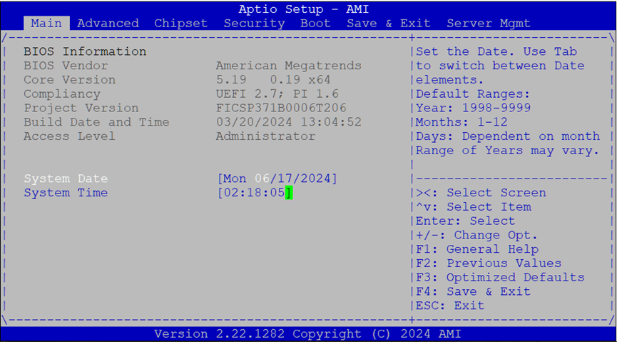
BIOS Information:
Vendor: American Megatrends
Core Version: AMI Kernel, CRB code base, X64
UEFI/PI Compliancy
Build Date and Time:
MM/DD/YYYYAccess Level:
AdministratororUser
Date & Time Setup:
Use
Tabto switch between year, month, day.Default year range:
2005–2099Day count depends on month selected.
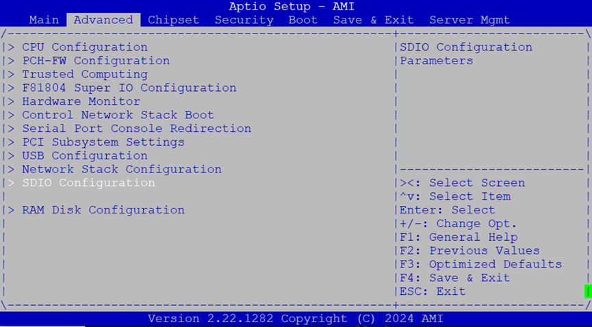
Advanced Tab
This tab provides access to configuration for CPU, chipset, PCIe, USB, and more.
Select Advanced from the top menu to enter.
CPU Configuration
This section allows you to adjust CPU-related features, including core count and diagnostic settings.

Options available:
Security Device Support: Enables or disables BIOS support for the TPM security device. If disabled, the OS will not detect the device. TCG EFI protocol and INT1A interface will also be disabled.
Active Processor Cores: Allows enabling a subset of the CPU cores (
All,1,2,3, etc.).BIST (Built-In Self-Test): Enables or disables a self-diagnostic test at system reset.
PCH-FW Configuration
Contains settings for the Platform Controller Hub firmware.
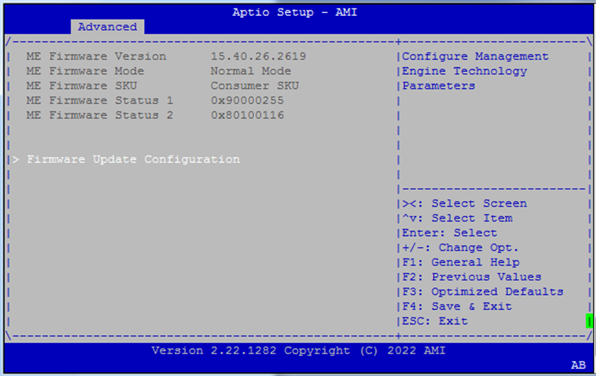
Firmware Update Configuration
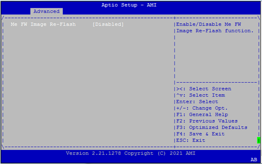
ME FW Image Re-Flash: Allows the firmware for the Management Engine (ME) to be updated from within BIOS. Use with caution in production environments.
Trusted Computing
Configure TPM support and related security hierarchies.
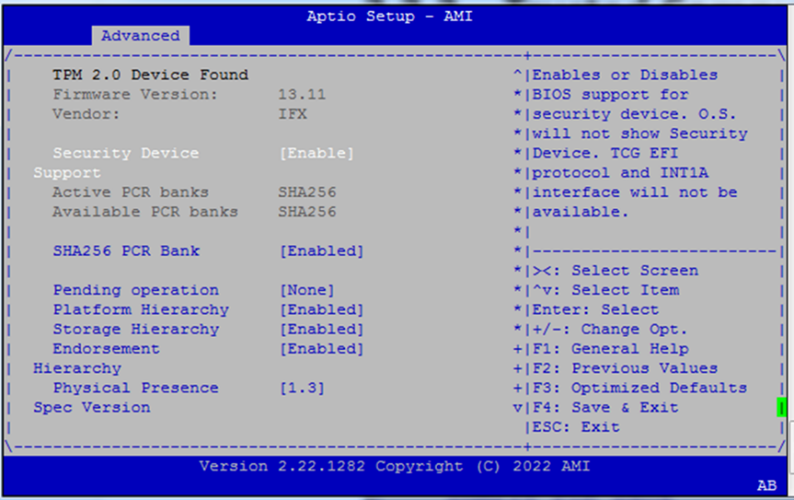
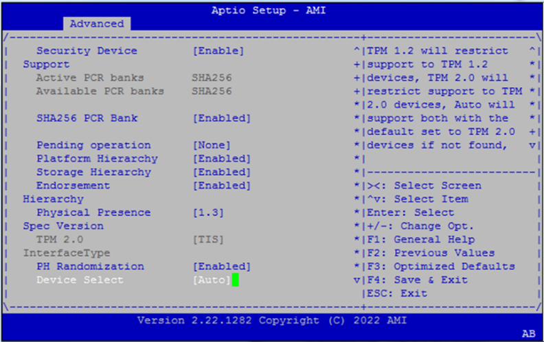
Options include:
Security Device Support
SHA256 PCR Bank
Pending Operation (e.g.,
TPM Clear)Platform / Storage / Endorsement Hierarchies
Physical Presence Spec Version (
1.2or1.3)PH Randomization (testing only)
Device Select:
TPM 1.2,TPM 2.0,Auto
Super IO Configuration
This section allows enabling/disabling onboard serial ports.
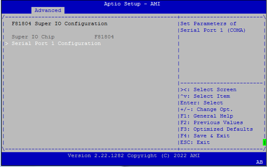
Serial Port 1 Configuration
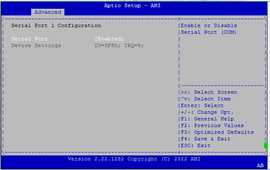
Serial Port (COM1): Enable if serial console access is needed.
Hardware Monitor
Real-time temperature and voltage readings.
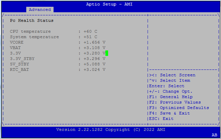
CPU Temperature
System Temperature
Voltage Rails:
VCOREVBAT3.3V3.3V_STBY5V_STBYRTC_BAT
Network Stack Boot Configuration
Configure which LAN interface to use for PXE or network stack booting.
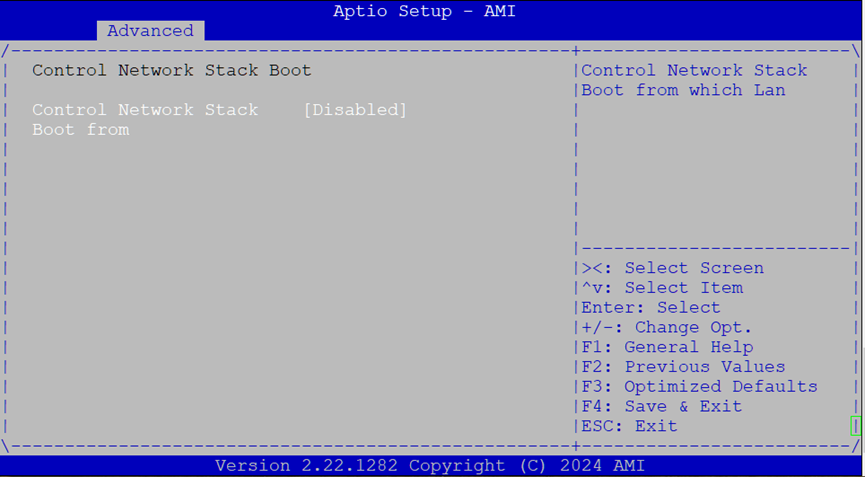
Control Network Stack Boot From: Options:
Disabled,LAN1,LAN2,LAN3
Use this setting if you’re using PXE boot or UEFI network boot.
Serial Port Console Redirection
Enables BIOS messages to be output to COM0, allowing headless remote management.
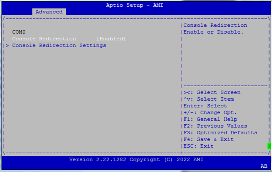
Console Redirection (COM0):
EnabledorDisabled
Useful for serial-over-LAN environments or embedded deployments.
Console Redirection Settings
Fine-grained settings for serial terminal behavior.
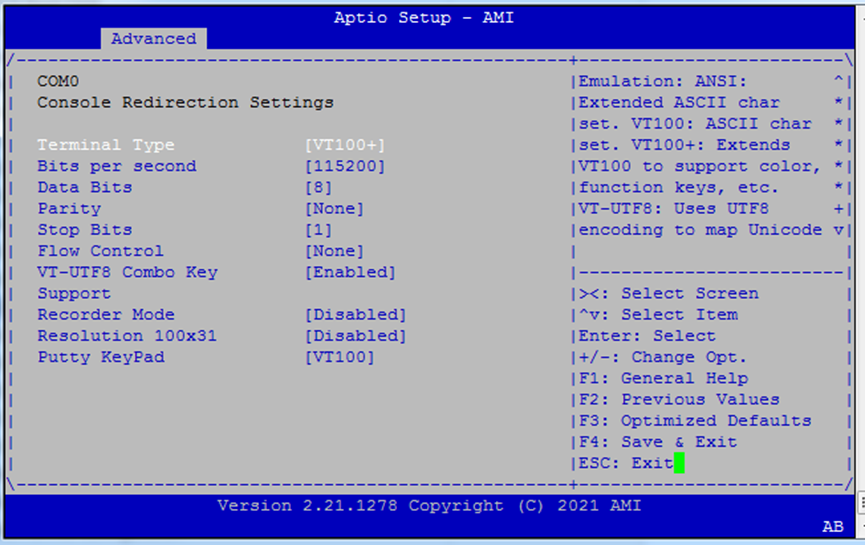
Settings:
Terminal Type:
VT100– BasicVT100+– Adds color, key supportVT-UTF8– UTF-8 supportANSI– Extended ASCII
Baud Rate: Options:
9600,19200,38400,57600,115200Data Bits:
7,8Parity:
None,Even,Odd,Mark,SpaceStop Bits:
1,2Flow Control:
None,Hardware,RTS/CTS
Match these with your serial terminal (e.g., PuTTY, TeraTerm).
VT-UTF8 Combo Key Support: Enables UTF-8 key combos (use only if terminal supports it)
Recorder Mode: Outputs text-only stream for logging
Resolution 100x31: Enables extended terminal size (100 columns × 31 rows)
Putty KeyPad: Choose from
VT100,LINUX,XTERM86,SCO,ESCN,VT400— sets keypad behavior
PCI Subsystem Settings
This section lets you manage virtualization features for PCIe devices.
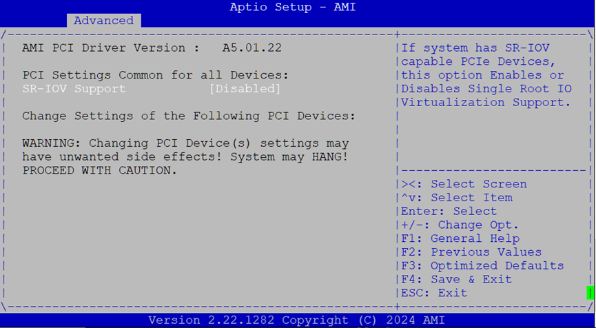
SR-IOV Support: Enable or disable
Single Root I/O Virtualizationfor supported PCIe hardware.
Only applicable if your expansion devices support SR-IOV (e.g., some NICs or FPGA cards).
USB Configuration
Configure USB behavior for both legacy and UEFI environments.
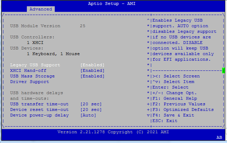
Key options:
Legacy USB Support:
Enabled: USB available for BIOS/OSAuto: Disable if no devices are presentDisabled: USB only available post-boot via UEFI
XHCI Hand-off: Enable if the OS doesn’t support USB 3.0 hand-off natively
USB Mass Storage Driver Support: Enables booting from USB drives
Transfer Timeouts:
Transfer:
1s,5s,10s,20sDevice Reset:
10–40s
Device Power-up Delay:
Autoor manual override per USB port
Network Stack Configuration
Enable UEFI booting over IPv4/IPv6 using PXE or HTTP.
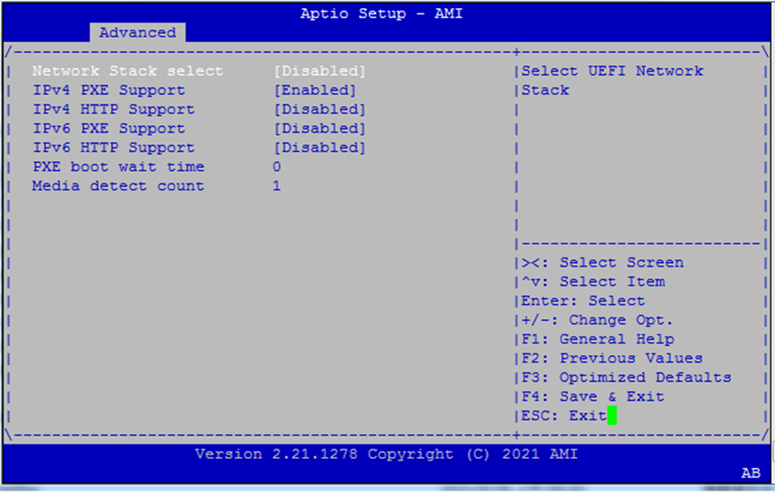
Settings:
Network Stack: Enable/disable the entire UEFI network stack
IPv4 PXE Boot / HTTP Boot
IPv6 PXE Boot / HTTP Boot
PXE Boot Wait Time: Seconds to wait for PXE boot before continuing
Media Detect Count: Number of retries to detect connected Ethernet media
SDIO Configuration
Adjust access mode for SD-based peripherals.
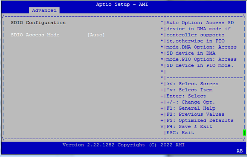
SDIO Access Mode:
Auto– Selects best mode automaticallyADMA,SDMA,PIO– Manual override modes for SD communication
Use
Autounless a peripheral requires a specific DMA mode.

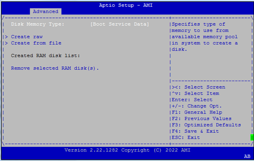
RAM Disk Configuration
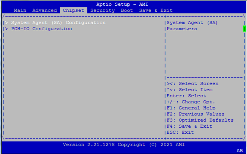
Chipset
Select the Chipset menu item from the BIOS setup screen to enter the “Chipset” setup screen.
Chipset: System Agent Configuration
System Agent handles CPU-integrated functions like memory, virtualization, and interrupts.
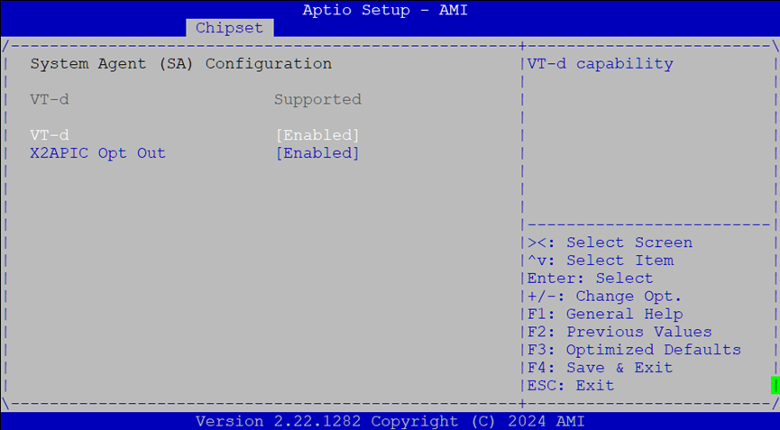
Settings:
VT-d: Enables Intel Virtualization for Directed I/O (IOMMU)
X2APIC Opt Out: Toggles compatibility with legacy APIC interrupt routing
PCH-IO Configuration
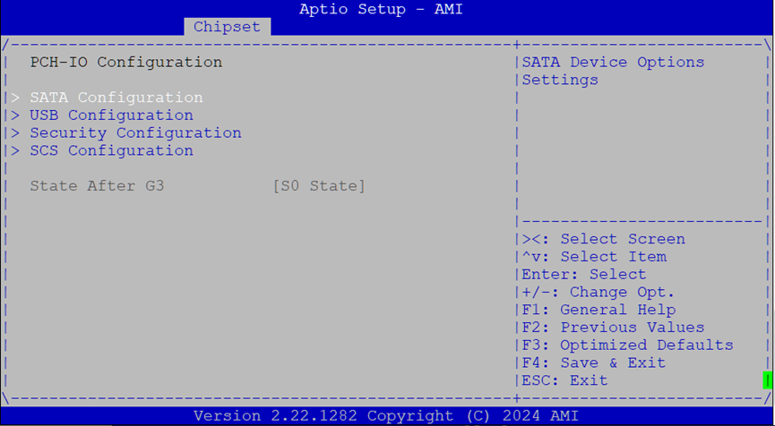
SATA Configuration
Configure how SATA ports behave.
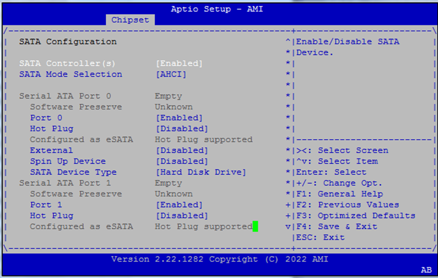
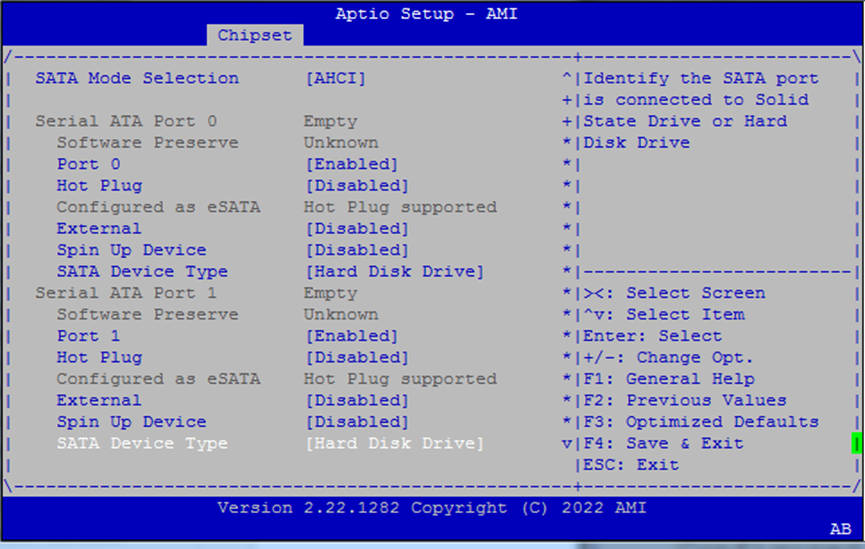
Main options:
SATA Controller(s): Enable/disable all ports
SATA Mode:
AHCI(default)Port 0: Toggle enable, hot plug, and external port settings
Spin-up Control: Allow staggered spin-up of SATA drives
Device Type: Choose
Hard Disk DriveorSolid State Drive
Use hot plug and external settings if you’re connecting removable drives or trays.
USB Link & xDCI Settings
Tuning options for USB 3.0/3.1 performance and OTG roles.
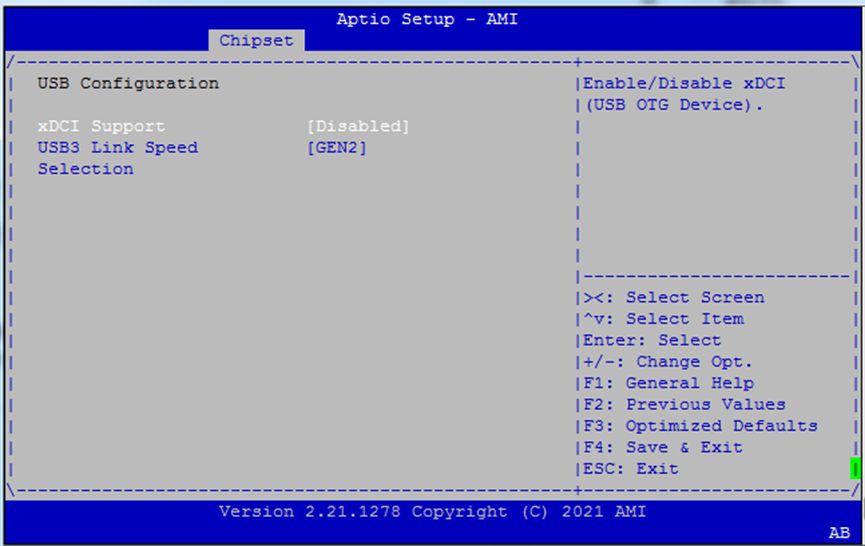
xDCI Support: Enables USB OTG functionality for embedded use cases.
USB3 Link Speed Selection: Choose
GEN1(5Gbps) orGEN2(10Gbps) for USB 3.1 devices.
Use
GEN1for legacy compatibility or signal integrity concerns.
Security Configuration
This menu allows you to configure low-level protection features related to RTC memory, BIOS write protection, and GPIO pad control.
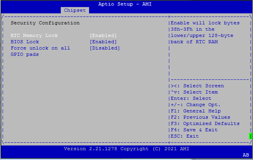
Options
RTC Memory Lock When enabled, locks bytes
38h–3Fhin both the lower and upper 128-byte banks of RTC RAM.BIOS Lock Enables the PCH BIOS Lock feature. Required for proper SMM-based protection of the flash region.
Force Unlock on All GPIO Pads If enabled, BIOS forces all GPIO pads to remain in the unlocked state.
Storage Controller Subsystem (SCS)
This section configures eMMC and SDCard controller options.
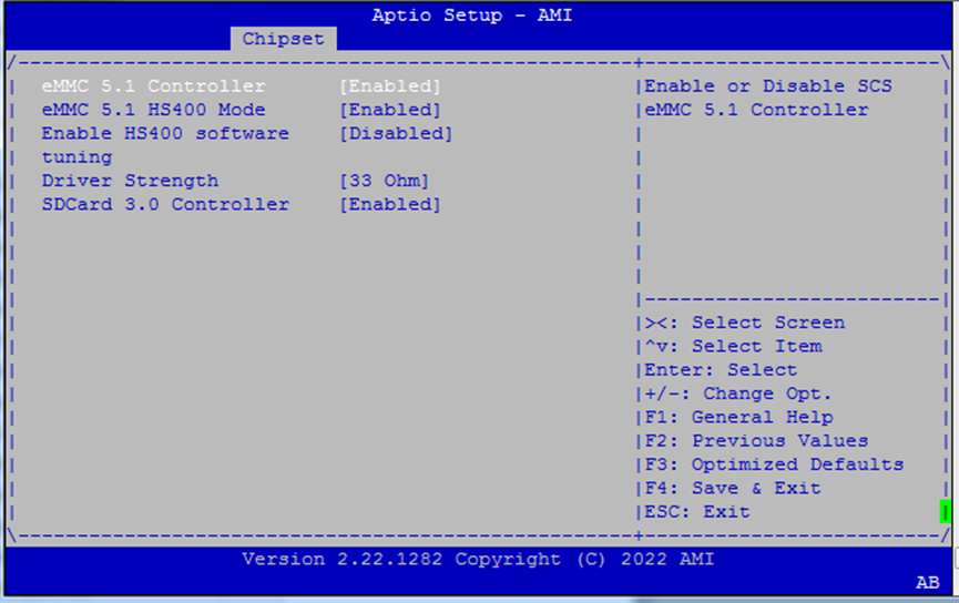
Options include:
eMMC 5.1 Controller: Enable/disable
HS400 Mode: Enables high-speed 400MB/s mode
HS400 Software Tuning: Improves signal stability
Driver Strength:
33Ω,40Ω, or50ΩSDCard 3.0 Controller: Enable SDIO interface
Use only if you’re booting or storing data on eMMC/SD devices.
BIOS Security Menu
Controls access restrictions and Secure Boot options.
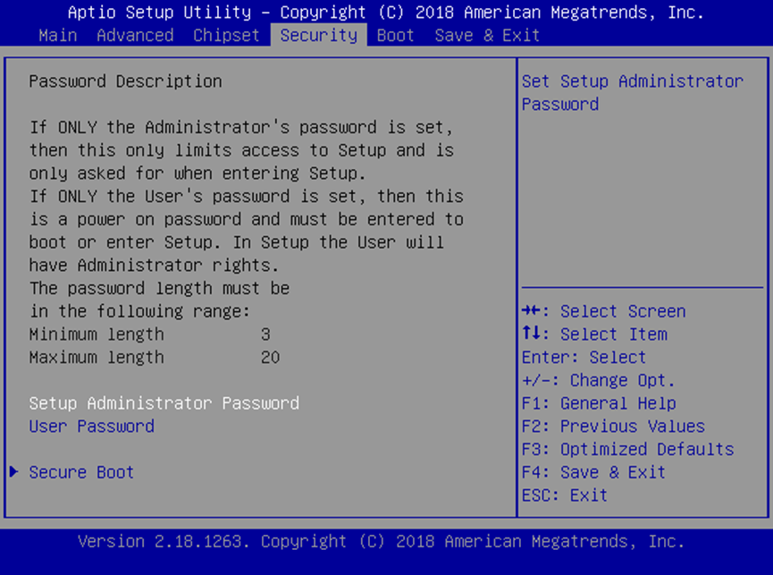
Setup Administrator Password: Required to enter and modify BIOS settings.
User Password: Required to boot or access BIOS, but grants admin rights once inside.
If only the User password is set, BIOS can still be entered but requires authentication.
Secure Boot Options

Secure Boot: Enables UEFI signature checking for OS bootloaders
Secure Boot Mode:
Standard(default keys) orCustom(user-defined PK, KEK, DB, DBX)
When Secure Boot is
Enabled, only signed UEFI images will be allowed to boot.
Key Management
Manage UEFI Secure Boot keys and certificates.
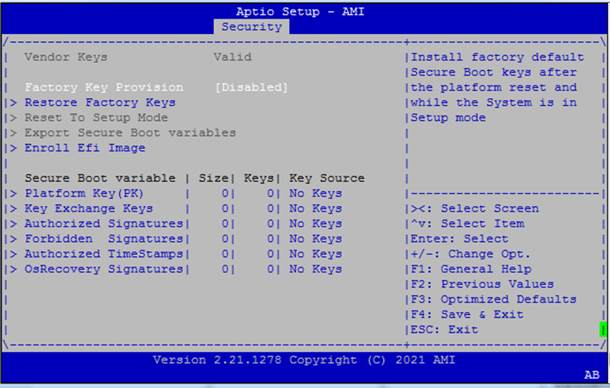
Options include:
Factory Key Provision: Installs the default platform keys (PK, KEK, DB, DBX)
Restore Factory Keys: Reverts to original keys after reset
Reset to Setup Mode: Deletes all Secure Boot key databases
Export Secure Boot Variables: Saves key info to a USB or other filesystem
Enroll EFI Image: Registers a specific EFI binary’s SHA256 into the
db(allowed list)
Use
CustomSecure Boot Mode to access these controls.
Boot Menu
Configure how the system boots.
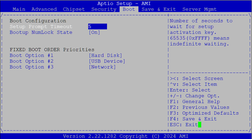
Main Options:
Setup Prompt Timeout: Delay (in seconds) to press BIOS access key
Bootup NumLock State: Enables or disables NumLock on startup
Boot Option Priorities: Set boot order for available storage/media devices
Use
+or-to reorder boot options.
Save & Exit Menu
Finalize BIOS changes or discard them.
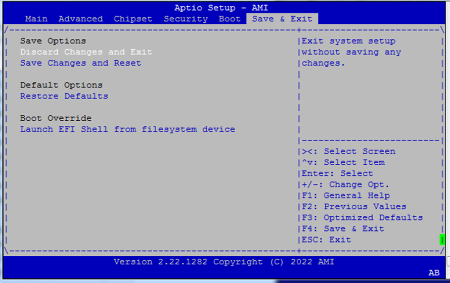
Available actions:
Save Changes and Reset
Discard Changes and Exit
Restore Defaults: Load factory-optimized settings
Note: Boot override entries appear at the bottom, depending on connected storage devices.